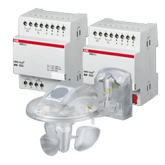
BUS sensors, actuators and displacement units
Different parts of BUS smart home equipment (Bms)
In the discussion of smart home equipment ,The transmission module determines the communication medium which the bus coupling unit will use. The most common bus coupling units are those with transmission modules for KNX TP (Twisted Pair) and for KNXPL (Powerline). The functions of these two types of transmission module are as follows:
- KNXTP:super imposing the data signal onto the DC supply voltage
- KNX PL:super imposing the data signal onto the 230 V mains power. Both types of transmission module also contain a power supply for the bus coupling unit controller, and generate reset and save pulses for the microcontroller. The bus coupling unit controller is essentially a microcontroller a chip incorporating a microprocessor and various memories and input and output peripherals.
The microprocessor will be a standard e.g. NEC, AT Mega or Texas Instruments controller with the following memories:
-
RAM: the smallest memory. Variable parameters generated during operation of the device are stored here.
-
EEPROM or flash memory: the data (e.g. parameters, physical addresses and group addresses) input by the user in the application software are stored in this memory. The contents of this memory are is downloaded from the PC to individual devices, to be programmed, where the data is then stored.
-
ROM: the system software for the bus coupling unit is stored in this memory, during production of the chip. There are already several different development levels and versions, known as masks. A mask consists of two bytes of data, the first digit of which – y – indicates what medium is used (0 for TP, 1 for PL110, 2 for RF and 5 for KNXnet/IP). Not all profiles exist on all of these media.
The last digit, x, identifies the profile version. The following masks serve to notify ETS of what system profile is used:
» y01xh: System 1
» y02xh: System 2
» y70xh: System 7
» y7Bxh: System B
» y300h: LTE
» 091xh: TP line/area couplers – repeaters
» 190xh: TP-PL110 media couplers
» 2010h: RF bidirectional Easy devices
» 2110h: RF unidirectional Easy devices
smart home equipment – for a long time, System 1 was the most common profile. However, Systems 2, 7 and B – a progression on System 1 – are now gradually replacing System 1. They offer more memory and so allow a larger number of Group Objects and Group Addresses to be used. All functions required for e.g. alarm systems have additionally been revised (e.g. data access management via password protection).(make smart )
Application software developed for System 1 can be downloaded to devices with a System 2 mask. Many suppliers of KNX devices now no longer offer any System 1 devices. Advanced bus devices use System 7 or B, which offers considerably more memory than even System 2. The 10 or 12- pin connection between the bus coupling unit and the bus end device can be used in very different ways depending on the requirements.
smart home equipment
Depending on the end device used, the data exchanged via the contacts can take the form of binary signals, analogue signals, or a data stream via a serial interface. The way in which the contacts is used is determined on the basis of a resistor in the end device, which is measured by the bus coupling unit. Some end devices have their own “intelligence”, possibly even in the form of another microcontroller. In this case the function of the bus coupling unit is often simply to manage the group addresses and ensure protocol compliant data traffic. In rare cases it does not even manage the group addresses, acting – like the serial interface – merely as a gateway to the KNX bus. System devices KNX system devices are devices that perform primarily special functions, e.g.
-
Facilitating adherence to the KNX topology
-
Power supply
-
Programming
KNX TP power supplies
KNX power supplies supply KNX TP lines with the necessary bus voltage, and provide the power needed for data transmission.
KNX TP USB interfacesf
A KNX TP USB interface is needed in order to program the KNX system from a computer.
KNX TP line couplers/area couplers
These devices are used for the coupling of KNX TP lines and areas. They can also act as line repeaters.
KNX PL band-stop filters
KNX PL band-stop filters prevent powerline telegrams from leaving the intended propagation range. They are single phase devices so should be fitted to all phases. Here it is important to adhere to the maximum current capacity of 63 A per device.
KNX PL phase couplers
In a three-phase network it should be ensured that KNX PL signals reach all three phases. If the three phases are routed in parallel in some sections, this will often take place automatically. If this is not the case, a phase coupler can help by providing capacitive coupling between the three phases of the 230 V network.
KNX PL system couplers
KNX PL system couplers can be used as repeaters for data signals in the 230 V network. They can also be used as line couplers for coupling several KNX PL lines, or as media couplers for coupling KNX PL systems with KNXTP systems.
KNX RF Media Couplers
KNX RF media couplers are used to couple KNX RF installations with KNX TP installations.
KNXnet/IP routers
KNXnet/IP routers support the protocols KNX IP routing and KNX IP tunneling, and can be used for coupling lines and areas. KNXnet/IP routers can also be used as a programming interface.
KNXnet/IP interfaces
KNXnet/IP interfaces are used for programming KNX systems from the Ethernet side.
KNX installation requirements
A KNX installation is a standard electrical installation in the 230 V range, so all requirements applicable to standard installations (VDE 0100, etc.) also apply to KNX. There are also some KNX-specific aspects to consider.
KNX TP
smart home equipment – No safety precautions are needed when installing/laying bus lines, because the bus voltage meets the requirements of safety extra-low voltage (SELV) and can therefore be touched. Because the absence of interference during the transmission of data between the individual bus devices depends on what cable is used, the KNX standard includes precise stipulations about what bus cables are acceptable.
The cable must be a shielded twisted pair cable (Table 1),
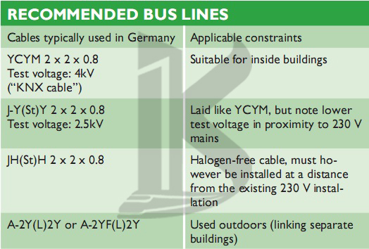
Table 1. What bus cable is used depends on the place of the installation.
smart home equipment- and the shielding on the cable must not be contacted or connected to earth on any side – it functions purely as a metal cage. In KNX TP, mains cables must not be used as bus lines because of the risk of confusion and their non-compliance with the applicable communication requirements.
Second twisted pair
The most common bus cables also include a second, free twisted pair. The following guidelines apply with regard to the use of this free pair:
- Only extra-low voltages (SELV/PELV) are permitted
- Max. 2.5 A continuous current, overload protection required
- Cannot be used as a circuit for public telecommunications networks
- The second twisted pair is used to provide a separate power supply for particularly power-intensive KNX devices.
Laying the cables
There are special issues to bear in mind wherever bus cables could come into contact with mains cables, e.g.
- In switch cabinets and distribution boards
- In branch boxes
Between the bus voltage and the 230 V network, double insulation capable of withstanding a test voltage of 4 kV is generally required. Minimum spacings apply, depending on the installation system used (Fig. 29).
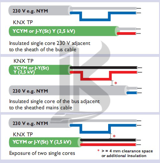
Figure 29. Minimum distances between bus cables and mains lines
If switch cabinets are used in which the mains section is fully separated from the installation bus (i.e. there must be no 230 V actuators present), then no special requirements apply. The shield of bus cables must continue right up to the terminals, and the use of shield bonding bars is not permissible.
Mains and bus cables should be routed and/or affixed in such a way that they do not touch. Special requirements apply for junction boxes only if both the bus cable and the 230 V cable are stripped. For branching, either separate boxes or a compartmentalized box with two separate chambers should be used.
Special requirements apply for “combinations”, i.e. where a bus component and a mains component are housed under the same cover, e.g. a flush-mounted actuator with a socket outlet controlled via the bus.
smart home equipment
When the common cover is removed, the mains side must remain covered, as is the case in socket outlets protected against direct contact. Bus cables should ideally be laid together with the mains and hence in the standard installation zones (for Germany see DIN 18015-3).
There are several different methods for routing bus cables in individual rooms: they can be arranged in a star topology around a central distribution board, or a ring topology passing through all of the rooms, or a combination of the two. An important aspect to consider before undertaking a KNX installation is the extent to which a conventional installation and a KNX installation should, or indeed can, be combined, e.g.(make smart home)
how appropriate it is to use KNX binary inputs in conjunction with conventional push buttons rather than KNX pushbutton sensors. This is particularly important if the customer has not yet fully decided on a KNX system, but would like to keep open the option of adding KNX components at a later stage.
There are essentially two ways to proceed here:
- Lay a bus cable now but add KNX components later
- Use a star topology for the conventional installation (e.g. wire each push button individually up to the distribution board), to allow the system to be retrofitted with KNX centrally in the distribution board.
It is therefore important to leave enough space in the distribution board.(smart home equipment)
