POSITIONING OF SMOKE & HEAT DETECTORS
To provide effective early warning of a developing fire situation, smoke detectors should be installed in all areas of the protected premises. Total coverage POSITIONING OF SMOKE HEAT and DETECTORS as defined by NFPA 72 should include all rooms, halls, storage areas, basements, attics, lofts, and spaces above suspended ceilings including plenum areas utilized as part of the HVAC system.
In addition, this should include all closets, elevator shafts, enclosed stairways, dumbwaiter shafts, chutes and other subdivisions and accessible spaces. Fire detection systems installed to meet local codes or ordinances may not be adequate for early warning of fire. Some codes or ordinances have minimum objectives such as capturing elevators or preventing circulation of smoke through the HVAC systems instead of early detection of fire.
A user should weigh the costs against the benefits of installing a complete fire detection system when any detection system is being installed. The location, quantity and zoning of detectors should be determined by what objectives are desired rather than the minimum requirements of any local codes or ordinances.
Detectors may be omitted from combustible blind spaces when any of the following conditions prevail:
1) Where the ceiling of a concealed space is attached directly to the underside of the supporting beams of a combustible roof or floor deck.
2) Where the concealed space is entirely filled with noncombustible insulation. (In solid joisted construction, the insulation need only fill the space from the ceiling to the bottom edge of the joist of the roof or floor deck.)
3) Where there are small concealed spaces over rooms, provided the space in question does not exceed 50 square feet (4.6 square meters). The number of heat and/or smoke detectors required in a given room will depend on the area and geometry of the room and the limitations of the equipment. All smoke detectors have similar spacing requirements; heat detectors also all have similar spacing requirements although these are different to smoke detectors.
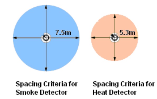
For general areas the spacing between any point in a protected area and the detector nearest to that point should not exceed 7.5 m for a smoke detector and 5.3 m for a heat detector.
The above are the maximum areas that can be covered by an individual detector. In order to ensure that coverage is provided into the corners of rooms and to ensure that there is no gap at the junction point of multiple detectors, spacings have to be reduced.
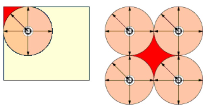
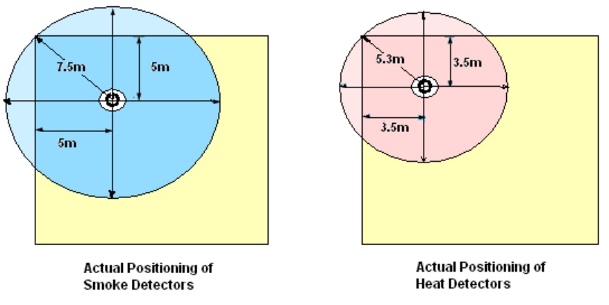
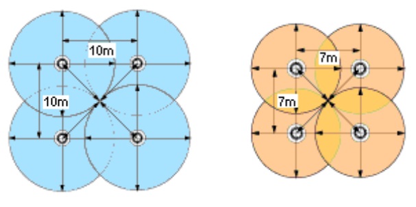
To ensure complete coverage for square layouts, spacings between detectors and walls should be reduced to 5 m for a smoke detector and 3.5 m for a heat detector.
To ensure complete coverage, spacings between detectors should be reduced to 10 m between smoke detectors and 7 m between heat detectors.
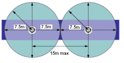
For corridors less than 2 m wide, only the centre line need be considered, therefore it is not necessary to reduce detector spacings in order to provide complete coverage. Therefore for smoke detectors spacing becomes 7.5 m from a wall and 15 m between detectors. For heat detectors, the spacing becomes 5.3 m to a wall and 10.6 m between detectors.
The above data is based on flat level ceilings; for pitched ceilings or ceilings with a non flat surface, spacings will alter. Where detectors must be mounted onto a pitched ceiling, a detector should be mounted near to the apex but spacing can be increased by 1% for each 1 degree of slope up to 25%. ‘Near’ is defined as within 600 mm for smoke detectors and within 150 mm for heat detectors. Note that some fire protection codes specify detector spacing on a given center to center distance between detectors under ideal conditions.
These spacing are based on rooms with smooth ceilings with no physical obstructions between the contents being protected and the detectors. Moreover, they are also based on a maximum ceiling height, and on the assumption that the value and the combustible nature of the contents of the room to be protected do not warrant greater protection or closer spacing.
Mounting Heights of Detectors
Under all normal circumstances point type fire detectors should be mounted on the ceiling. This ensures that the height restrictions are met together with the following table.
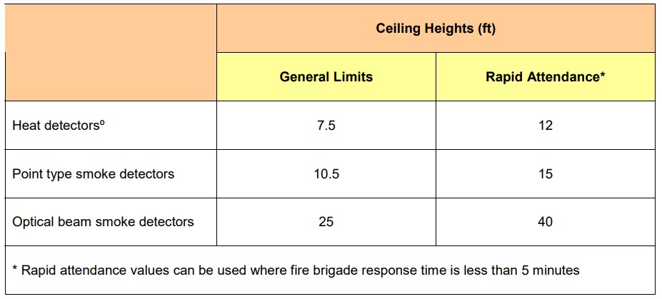
1 Rapid attendance values can be used where fire brigade response time is less than 5 minutes
2 According to NFPA 72 2002 table 5.6.5.5.1, heat detector spacing is reduced on ceiling heights that exceed 10 feet. All detectors (heat and smoke) shall be accessible for service and replacement. Installation must include service and replacement. Installation must include the ability to get at the smoke or heat detector. Concealed detectors must be prominently indicated as required in NFPA 72 (section 3-8.4)
Beams and Other Similar Ceiling Obstructions:
Fire detectors should be mounted at least 500 mm away from walls or ceiling obstructions greater than 250 mm deep and at least twice the depth of obstructions less than 250 mm deep. They should also be mounted at least 3 ft (1 m) away from any forced air inlet. Where the obstruction is greater than 10% of the height of an area, it should be considered as a wall. Similarly a floor mounted obstruction (such as racking) should be considered a wall if it comes to within 300 mm of the height of the detector.
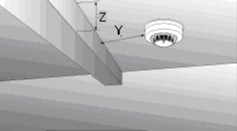
For obstructions of less than 250 mm Y should be at least 2 x Z Lift Shafts:
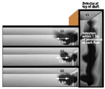
Where detection is required in vertical shafts, such as stairwells, a detector should be mounted at the top of the shaft and within 1.5 m at each level.
Recommendations for Smoke and Heat Detectors in Houses
With regard to the number and placement of smoke/heat detectors, subscribe to the recommendations contained in the National Fire Protection Association’s (NFPA) Standard #72. Early warning fire detection is best achieved by the installation of fire detection equipment in all rooms and areas of the household as follows: For minimum protection, a smoke detector should be installed outside of each separate sleeping area and on each additional floor of a multi-floor family living unit, including basements. Note the general guidelines below:
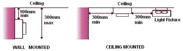
1) Your smoke detector should be positioned in your house ideally on the ceiling, or on the wall, between 4-6 inches away from the ceiling-wall intersection. Be sure to place your smoke detector:
• On the ceiling, at least 12 inches away from the wall. A fire can often “trap” pockets of air where the wall and the ceiling meet — smoke might never reach the smoke detector in this “dead air space” 20 feet away from “sources of combustion particles” (stoves, furnace, and water heater).
• More than one foot away from fluorescent lights.
• If the ceilings are sloped, peaked, or gabled, mount 3 feet from the highest point of the ceiling.
2) Detectors should not be located near openable windows, supply duct outlets, or other ventilation sources that would interfere with the natural air currents nor near any obstruction that would prevent smoke or heat from reaching the detector. Drafts can blow the smoke away from the smoke detector, preventing the smoke detector from sounding. Placement of detectors near air conditioning or incoming air vents can also cause excessive accumulation of dust and dirt on the detectors. This dirt can cause detectors to malfunction and cause unwanted alarms. When air supply and/or air return ducts are present in a room or space, the detector(s) should be placed in the path of the air flow toward the return air duct. Smoke detectors must be at least:
• 4 feet from ceiling supply air diffusers
• 10 feet from wall supply air diffusers.
Spot type detectors, in properly engineered systems, may also be placed in return air ducts, or in approved duct detector housings designed for this application. Although duct detectors are not a substitute for open area detectors, they can provide an effective method of initiating building control functions to prevent smoke from being transported from the fire area to other parts of a building.
Smoke tests are helpful in determining proper placement. Special attention should be given to smoke travel directions and velocity, since either can affect detector performance.
3) “Total coverage”, as defined in NFPA 72, is the definition of a complete fire detection system. In some of the specified areas of coverage, such as attics, closets, under open loading docks or platforms, a heat detector may be more appropriate than a smoke detector. The installation of smoke detectors in kitchens, attics (finished or unfinished), or in garages is normally not recommended. A smoke detector too close to the kitchen might frequently signal false alarms.
4) Detectors are usually required or recommended underneath open loading docks or platforms and their covers, and in accessible under-floor areas in buildings without basements.
Detectors may be omitted from combustible blind spaces when any of the following conditions prevail:
• The space is not accessible for storage purposes; it is protected against the entrance of unauthorized persons, and it is protected against the accumulation of windblown debris.
• The space contains no equipment or structures (such as steam pipes, electrical wiring, ducts, shafts, or conveyors) that could potentially ignite or conduct the spread of fire.
• The floor over the space is tight.
• Nonflammable liquids are processed, handled, or stored on the floor above the space.
5) In general, when only one detector is required in a room or space, the detector should be placed as close to the center of the ceiling as possible. Central location of the detector is best for sensing fires in any part of the room. If a center location is not possible, it may be placed no closer than 4 inches from the wall, or if listed for wall mounting, it may be mounted on the wall. Wall mounted detectors should be located approximately 4 to 12 inches (10 to 30 cm) from the ceiling to the top of the detector, and at least 4 inches (10 cm) from any corner wall junction.
6) For additional protection, the NFPA recommends that you install heat or smoke detectors in the living room, dining room, bedroom(s), kitchen, hallway(s), attic, furnace room, utility and storage rooms, basements, and attached garages.
Where Not To Place Detectors
One of the major causes of unwanted alarms is improper placement of detectors. The best way to avoid unwanted alarms is not to install detectors in environments that can cause them to malfunction, or to install detectors specially designed for those environments. Typical examples are:
1. Outdoors
Avoid using detector outdoors, in open storage sheds, or other open structures affected by dust, air currents, or excessive humidity and temperature extremes.
2. Wet or Excessively Humid Areas
Avoid damp, wet or excessively humid areas, or next to bathrooms with showers. Water droplets can accumulate inside the sensing chamber and make the detector overly sensitive.
3. Elevator Lobbies
Do not place over ash trays or where people will smoke while waiting for the elevator.
4. Extreme Cold or Hot Environments
Avoid very cold or very hot environments, or unheated buildings or rooms where the temperature can fall below or exceed the operating temperature range of the detector. At temperatures below 0°C (32°F)*, ice crystals or condensation can appear inside the sensing chamber and make it overly sensitive or cause a false alarm. At temperatures above the operating range of the detector (greater than 49°C or 120°F), its internal components may not function properly.
5. Areas with Combustion Particles
Avoid areas where combustion particles are normally present, such as in kitchens or other areas with ovens and burners; in garages, where particles of combustion are present in vehicle exhausts. When a detector must be located in or adjacent to such an area, a heat detector may be appropriate.
6. Manufacturing Areas
Avoid manufacturing areas, battery rooms, or other areas where substantial quantities of vapors, gases, or fumes may be present. Strong vapors can make detectors overly sensitive or less sensitive than normal.
• In very large concentrations, gases heavier than air, such as carbon dioxide, may make detectors more sensitive, while gases lighter than air, such as helium, may make them less sensitive.
• Aerosol particles may collect on detector chamber surfaces and cause nuisance alarms.
7. Fluorescent Light Fixtures
Avoid placement near fluorescent light fixtures. Electrical noise generated by fluorescent light fixtures may cause unwanted alarms. Install detectors at least 1 foot (3 m) away from such light fixtures. In general, unless specifically designed for the condition, smoke detectors shall not be installed if: a) temperature is below 32°F or above 100°F, b) Relative humidity is above 93 percent, and c) Air velocity is greater than 300 feet per minute. Also detectors shall not be installed until after the construction cleanup of all trades is complete and final.
See Table A-5-3.6.1.2A in NFPA 72-1996 for further details.
MANUAL CALL POINTS
Manual call points or pull stations allow building occupants to signal that a fire has been observed as they leave a building. The general design philosophy is to place stations within reach along paths of escape. It is for this reason that they can usually be found near exit doors in corridors and large rooms. The selection of manual call points is somewhat simpler. Surface or flush types are selected depending on the environment and whether the fire system is being installed into an existing building (where surface call points are generally easier to install).
Standard call points use a frangible glass element which is designed to break under light pressure triggering the call point into an alarm condition. The glass element is covered with a thick plastic film to protect the operator against broken glass, however plastic resettable elements and protective flaps can be used where there is the risk of unwanted operation or in food preparation areas. Where hinged covers are used these should be recorded as a design variation.
Call points can be supplied with LED indicators mounted onto the front face to simplify the location of an operated call point.
The call point for use in open circuit systems contains contacts held open by the pressure of the front plate. Breaking the plate closes the contacts and initiates an alarm. Call points for closed circuit systems operate in the reverse manner, the contacts being held in the closed position and open upon the breaking of the front plate. Alarm testing facilities are normally provided for open circuit points. Closed circuit points do not necessarily require this facility since the circuits are continuously under test.
The advantage of manual alarm stations is that, they are simple devices, and can be highly reliable when the building is occupied.
The key disadvantage of manual stations is that they will not work when the building is unoccupied. They may also be used for malicious alarm activations. Nonetheless, they are an important component in any fire alarm system.
General Guidelines on the Manual Call points
1) The height of the manual fire alarm boxes shall be a minimum of 42 inches (1067 mm) and a maximum of 54 inches (1372 mm) measured vertically, from the floor level to the activating handle or lever of the box. Manual fire alarm boxes shall be red in color.
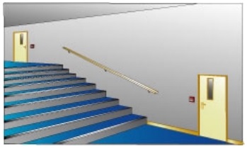
2) Manual call points should be located on escape routes, at all exits from each floor at the stair and corridors.
3) Manual fire alarm boxes (pull station) should be located not more than 5 feet (1524 mm) from the entrance to each exit.
4) Manual call points should be located at each door opening to the exterior of the building.
5) Manual call points should be located at the exit from each High-Hazard Occupancy (High-Hazard as defined by NFPA 101).
6) Manual pull stations should be located so that the travel distance to any station from any point in the building does not exceed 200 feet.
7) Manual pull stations should be located at each exit from an Assembly Occupancy (Assembly Occupancy as defined by NFPA 101).
8) Manual fire alarm boxes should be located in each story including basements. In buildings of Assembly Use Group, a manual fire alarm box shall be located next to the lighting control panel.
9) Manual call point should be located where required by NFPA 72.
10) Manual pull stations should be installed 42 to 54 in above the finished floor. All manual pull stations should be located to be readily accessible, unobstructed, and visible.
11) For general applications, call points should be located such that no one needs to travel more than 45 m to reach the nearest call point. This distance is based on measuring the actual route that would be travelled. If at the design stage the actual layout is unknown, then a straight-line distance of 30 m should be used as a design guide and the 45 m limit verified after fit out is complete.
NOTIFICATION DEVICES
Upon receiving an alarm notification, the fire alarm control panel must now alert someone that an emergency is underway. Fire alarm systems utilize a variety of devices to alert building occupants and fire authorities within the protected area as well as outside that an event or fault has occurred. These devices include:
1) Audible alarms (horns, bells, buzzers, chimes, etc.)
2) Visual alarms (strobes, etc.)
3) Voice Evacuation systems
Alarms
The audible types are most common, with a variety of types being available from bells to all kinds of different electronic sounders including those containing pre-recorded spoken messages. Many types of alarm sounders are available and the choice of device is dependent on local preference, legal requirement and the need to have a tone distinct from all other building audible alarms.
1) Bells are the most common and familiar alarm sounding device, and are appropriate for most building applications.
2) Horns are another option, and are especially well suited to areas where a loud signal is needed such as library stacks, and architecturally sensitive buildings where devices need partial concealment.
3) Chimes may be used where a soft alarm tone is preferred, such as health care facilities and theaters.
4) Electronic solid state sounders with mono or multi tone output normally in the range of 800 to 1000 Hz.
5) Small sirens operating in the range of 1,200 to 1,700 Hz. Sirens ranging widely in size from 0.17 to 11 kW generally operating in the frequency range of 400 to 800 Hz. Outdoor sirens should be fitted with heaters and thermostats to protect against low temperature conditions.
6) Speakers are the fourth alarm sounding option, which sound a reproducible signal such as a recorded voice message.
7) Voice communication capabilities can be integrated into a fire alarm system by connecting loudspeakers or public address (PA) systems located throughout the building to a central control. In these cases, the audible alarm signal operates for a predetermined period of time, after which it can be silenced while the loudspeakers are in use. These systems enable fire department personnel to instruct the building occupants on procedures to follow during the fire. They are often ideally suited for large, multistory or other similar buildings where phased evacuation is preferred.
Sound levels should generally be 65dBA or 5dBA above persistent background noise levels. This may be reduced to 60dBA in rooms smaller than 600 ft2, in stairwells or in specific limited points of the building. Most sounders have adjustable output levels, which allow a balance between meeting the requirements of the standard and providing a sensible level of audible comfort. Generally more low output sounders are better than few high output sounders in this respect.
In addition to these general requirements the following specific requirements should also be noted:
1) A level of at least 75dBA at the bed head is required to wake sleeping occupants.
2) At least one sounder is required per fire compartment.
3) All of the sounders utilized in a building should emit a similar noise.
When considering the number and position of sounders the following should be considered:
1) A loss of at least 20 to 30dBA should be allowed for sound going through doors.
2) Where two identical sounders are in one location the level increases by only 3dBA.
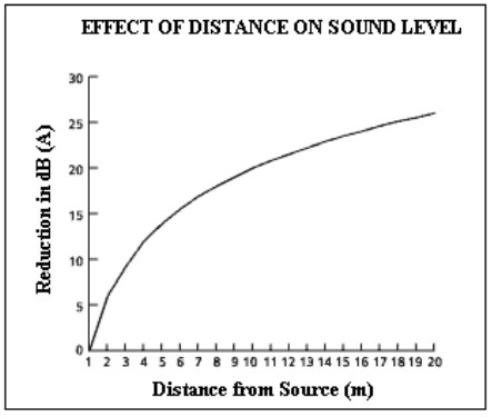
3) The sound pressure level drops with distance according to the graph below.
4) It is necessary to consider cable loading requirements when designing sounder circuits. Volt drop should be limited to less than 10% of nominal voltage.
5) It is recommended to always err on the side of caution when selecting sounders and their locations, as it is far simpler to reduce the volume setting of a sounder where appropriate than to retrofit additional sounders should the initial levels be inadequate. Sounder output levels are normally quoted in dB (a) at 1m.
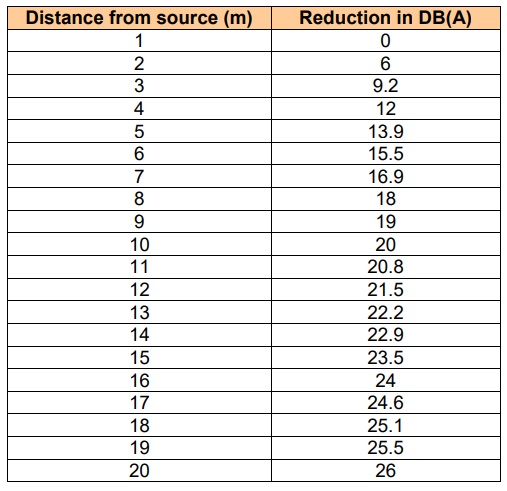
The graph below can be used to calculate effect on sound level at other distances in free air. In addition allowances have to be made for obstructions such as doors, the absorption of sound by furnishings the directional nature of the sounder, mounting position and location of the sounder, etc.