Smart Thermostat Control Methodologies in HVAC
Once upon a time, air conditioner thermostats were simple mechanical devices that relied upon principles like the deflection of temperature sensitive metal in order to signal when a unit needs to switch on and off. Not only are air conditioner smart thermostat now electronic and programmable, but the use of variable capacity inverter compressors in an increasing number of packaged air conditioners and other types of equipment is demanding additional complexity of smart thermostat control systems. This is because reliable control algorithms that are more complicated than traditional on/off logic are essential for modulating the output of these modern air conditioning units accurately and stably with respect to a heating or cooling load.
Recognizing the importance of proper smart thermostat control is paramount, as the benefits of the latest and greatest air conditioning hardware (like improved temperature control precision and energy efficiency for example) can be negated without adequate “brainpower” driving it. Improper control can even be detrimental to variable capacity equipment, with haphazardly controlled compressor speeds or on/off cycling leading to increased wear. This article will therefore cover the basics of common thermostat control methodologies, along with an overview of the Air Change control approach which is included with the ClimaSync Control System.
Traditional Fixed Capacity Control
The focus of this article is on variable capacity control methodologies, however for background knowledge it will be beneficial to cover how traditional fixed capacity smart thermostat systems work.
Fixed capacity systems require a temperature hysteresis (also commonly referred to as a dead band) to accompany the setpoint temperature. This hysteresis is a window where in which the on/off control state of the air conditioner compressor does not change and allows the room temperature to be maintained within an acceptable tolerance.
For example, the below cooling scenario in figure 1 shows a compressor operating until the room temperature meets the lower hysteresis limit of 23°C. The compressor then switches off until the room warms to the upper hysteresis limit of 25°C where the compressor switches back on again, and the cycle continues for as long as the space requires cooling. This results in an average room temperature that is equal to the required setpoint temperature of 24°C, however the inherent temperature fluctuation may not be acceptable for mission critical applications.
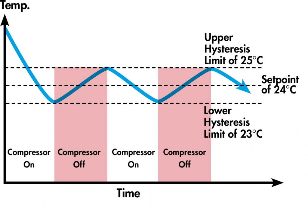
Figure 1: Fixed capacity temperature control.
PID Control
PID controls are the most conventional and widely used algorithms for not only variable capacity smart thermostats, but also other machine processes in general that require modulating control. They are feedback loops that continuously calculate the error between a desired setpoint and the current measured condition, and then use well-known mathematical principles that deal with continuous change to generate a control output that is suitable for correcting the error.
The below schematic demonstrates the basic operating principle of a PID loop used in a variable capacity smart thermostat application, where the PID controller continuously calculates the control output (eg. variable 0-10V compressor speed signal) required to maintain the air temperature at the setpoint.
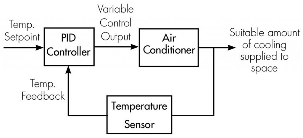
Figure 2: PID loop schematic for variable capacity air conditioner control in smart thermostat
The name PID stands for Proportional, Integral, and Derivative which refer to the three types of mathematics that govern the control output. For those of you who want to dust off your old calculus textbooks, the mathematical function of control output u(t) with respect to the measured error e(t) is expressed below (there are often variations in representation, but the underlying principle remains the same).
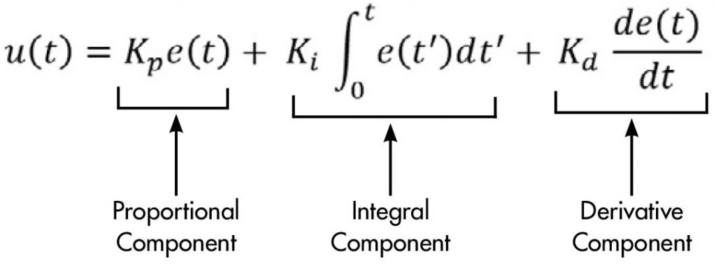
Figure 3: PID mathematical equation.
The role of each of the PID components is as follows.
Proportional
The proportional component of PID draws upon the present to influence the control output proportionally to the error. Its effects are most relevant when the error between the setpoint and measured condition is large.
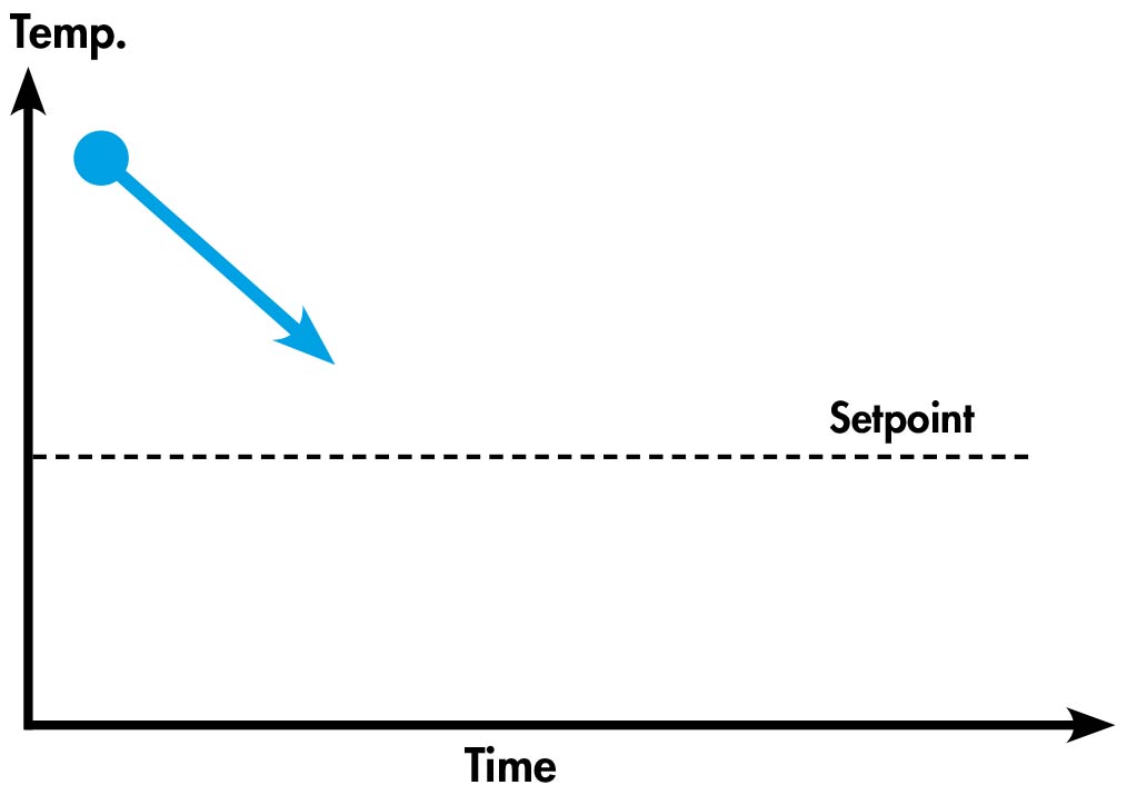
Figure 4: Effect of proportional component in PID control.
Integral
The integral component of PID uses integral calculus to draw upon the past and its influence on the control output helps the measured condition meet the setpoint in a stable manner.
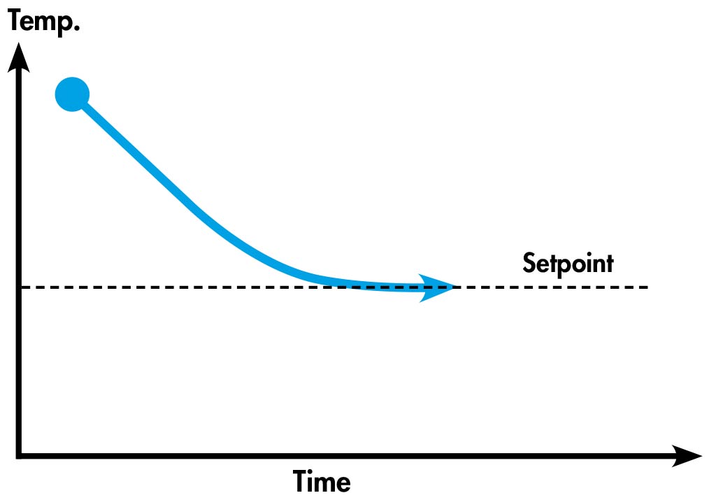
Figure 5: Effect of integral component in PID control.
Derivative
The derivative component of PID uses derivative calculus to forecast into the future and its influence on the control output helps minimise overshoot of the setpoint which improves stability.
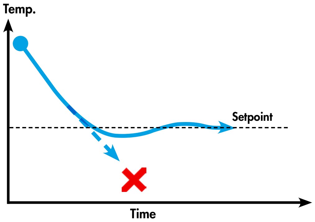
Figure 6: Effect of derivative component in PID control.
Each of the PID components include a coefficient (Kp, Ki & Kd) which need to be tuned to a particular application for optimal performance. A well-tuned system will have a fast settling time along with little to no temperature oscillation around the setpoint. However, the dynamic loading and non-linear control nature (meaning that control outputs aren’t proportional to the actual resulting process effect) of HVAC systems makes achieving optimal PID tuning difficult and performance can vary. Despite this, PID controls are widely used in HVAC equipment because they are relatively simple to implement.
Fuzzy Logic Control
Fuzzy logic is another common smart thermostat control methodology for variable capacity air conditioners that could be considered to be less purely calculative and more heuristic than PID control. It is a concept that is probably easiest explained through an example:
Step 1: Fuzzification
The initial step involves taking “crisp” control inputs and then “fuzzifying” them by mapping them onto a pre-constructed fuzzy set which consists of membership functions. For example, a measured room condition of 30°C is classified as mostly “Scorching” where the degree of membership is 0.5, and a bit “Hot” where the degree of membership is 0.25.
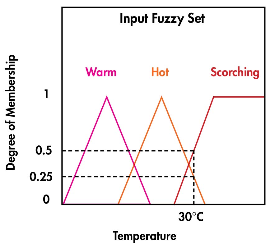
Figure 7: Control input fuzzy set.
Step 2: Fuzzy Inference
The next step involves using predetermined rules that govern what the required “fuzzy” response needs to be. The rules that would likely apply to a scenario like this would be:
-If room temperature is scorching, then compressor speed needs to be fast.
-If room temperature is hot, then compressor speed needs to be medium.
-If room temperature is warm, then compressor speeds needs to be slow.
In this case, as the room temperature is determined to be mostly “Scorching” and a bit “Hot”, the system response needs to be a mixture of “compressor speed needs to be fast” and “compressor speed needs to be medium”.
Once the appropriate fuzzy outputs are determined through the inference rules, the degree of membership for the control inputs can be mapped onto a separate fuzzy set for the corresponding control outputs.
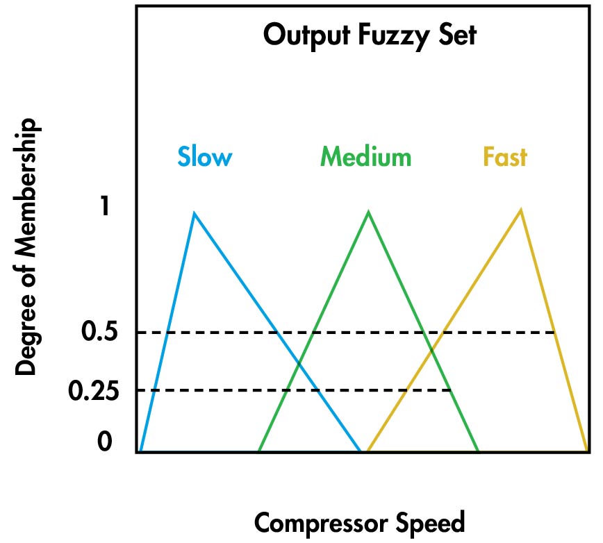
Figure 8: Control output fuzzy set.
Step 3: Defuzzification
The defuzzification step involves converting the “fuzzy” output into a “crisp” output that the air conditioner can use (eg. compressor revolutions per second). There are numerous methods of achieving this, however the centroid approach is a popular one. In this case, the centroid of the active portions of the Medium and Fast membership functions equates to a compressor speed of 85 RPS.
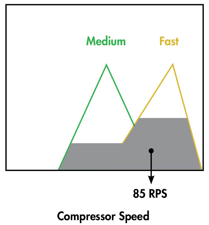
Figure 9: Defuzzification by centroid method.
Fuzzy logic is a design-flexible approach with numerous factors like the number of fuzzy sets (for multiple control inputs/outputs), the shape of membership functions, the inference rules, and the defuzzification method all contributing to the behaviour of the system and how well it performs. Well-developed fuzzy controls can be designed around the dynamic and non-linear control nature of HVAC systems which results in very good performance, but they can also consequently become quite complex. Development of fuzzy controls also requires high prescriptive knowledge of how a system should behave in certain scenarios, which could possibly lead to uncertainty of performance in untried situations.
“This article was written by Matthew Gellert who is a Business Development Engineer at Air Change.”
*********
Heating control in intelligent building with KNX technology
The experimental set-up realized in Electric System KNX Installation Laboratory allowing investigating and testing the economy of heat energy using control of building installation is presented. Estimation made for Laboratory indicates that heating control reduces energy
about 26% in relation to heat energy without control. The function schemes of control and a way of programming are described.
Introduction
Instabus KNX allows heating control taken into account individual requirements and energy efficiency. These are the most important reasons to use local temperature control. This mode of control is used in residential buildings, office buildings, schools, public buildings and industry. Individual controllers permit differ temperature in each room or group of rooms increasing comfort and decreasing or saving building exploitation costs. In Poland the most important are the costs of heating. Evidently, these costs depend on building construction technology and mode of heating control. Using KNX system this control is very developed and easy to employ but unfortunately it is very expensive. Therefore, in KNX Installation Laboratory in Institute of Electric Power Engineering the experimental and theoretical investigations are planed and we expect determine how much energy can be saved using heating control.
KNX HVAC Control
First, heating control and test will be realized only in KNX Installation Laboratory using 4-push-button, LCD-mini-panel and EMO valves. Nowadays, the temperature control with electromotive valves is often connected with control and monitoring of heating boiler equipped with interface to the KNX. In this situation the individual temperature sensor controls electromotive valves adequately the user’s requirements and in addition the signal of valve status position influences on parameters of heating boiler. Depending on status position of all valves in the building, boiler automatically adapts output temperature of heating medium to building needs controlling circulation pump and burner. We will test this mode in future for heating system in one of the buildings of Electric Power Engineering Institute.
In this paper we present theoretical estimation how much energy we can economize using heating control. The mode of control in KNX Installation Laboratory allowing the tests is also presented.
Algorithm of heating control
The heating systems are equipped in time and temperature controllers but these controllers can not be integrate with KNX system and combined to scenes with building installations, which are achieve using KNX standard installation. The block-box scheme of temperature control is shown in Figure 1. The main element of system i.e. controller receives telegram from temperature sensor placed in room, compares with set value and manages temperature depending operational mode.
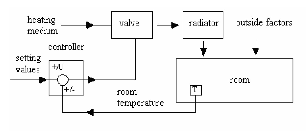
Fig. 10. Block-box scheme of temperature control in smart thermostat
Different temperature management algorithms are used. The simplest is that two steps realized using thermoelectric valve. The controller switches on and off depending on temperature passing up or below set temperature value. In this case the output value is not calculated. The large inertia with ambient temperature changing is inconvenient, therefore, this management mode can not be used for inert systems as for example underfloor heating.
In this situation Proportional-Integral (PI) algorithm is more adequate. It requires electromotive valve with lift detection. Using thermoelectric valve the Pulse Width Modulation (PWM) algorithm can also be used allowing adjusting of heating control. In experimental set-up the temperature will be controlled using electromotive valve. Apart of PI algorithm, two-step control will be also realized to estimate heating parameters for different algorithms.
Calculation of heat loss
Economy of heat energy can be achieved using following solutions:
1. Control of ventilation during changing air in the room. Cold air introduced into the room is
heated by warm air extracted from room reducing energy required to heat.
2. Control of warm water flow, for example switching on a circulation pump at the moment of
water usage.
3. Individual temperature control in the rooms. Our calculation takes into account only the possibility of energy reducing by individual temperature control.
Computations have been performed for KNX Installation Laboratory placed in building in such a way that three walls are exterior and only one is interior. Ceiling and floor are interior.
Laboratory surface is 42 m² and its volume 126 m³. The building is construct with brick and non-isolated. Calculations are performed considering outdoor temperature -18°C and temperature in adjoining to laboratory rooms is 20oC.
The scene for temperature control is as follow:
– on day – from 8h to 18h the temperature is 20°C,
– at night – from 18h to 7h the temperature is 12°C,
– between 7h and 8h the temperature rise from 12°C to 18°C.
Installation equipment and programming
Hating control in KNX Installation Laboratory is realized using:
– Merten multi-function 4-push-button with room temperature control unit (Fig. 11a) and room smart thermostat placed near the window,
– Merten LCD-mini-panel placed near entrance to laboratory (Fig.11b).
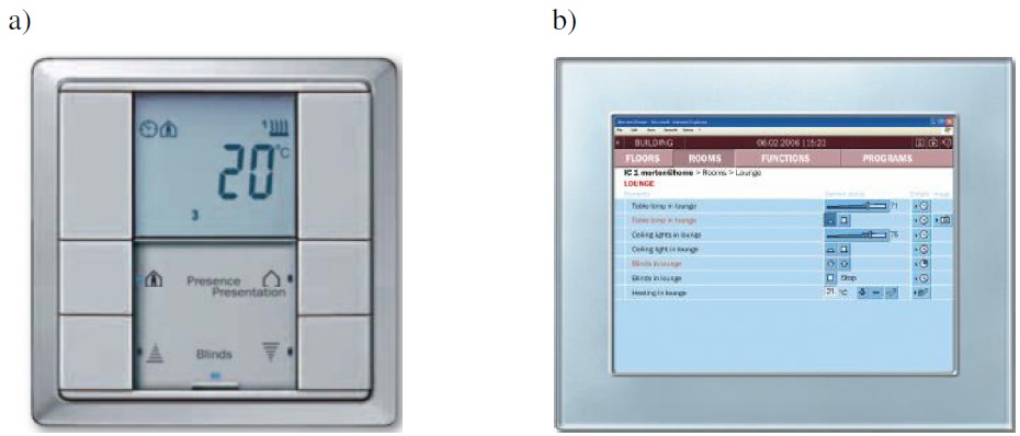
Fig. 11. Merten KNX apparatus [3]: a) multi-function 4-push-button, b) LCD-mini-panel
Heating functions in laboratory are programmed for push-button P1 (Fig. 11a) with temperature control unit allowing 2-step control, continuous PI control or switching PWM control. Operating modes are: comfort, standby, night economy, frost/heat protection. The parameters and functions of operating modes are set as follow:
comfort
temperature set to 20ºC in time interval from 8.00 to 18.00, function activated using telegram „ON” – „1”,
standby
temperature set to 18ºC in time interval from 7.00 to 8.00, function activated using telegrams: switch off “comfort” operating mode „OFF” – „0” and “night” operating mode „OFF” – „0”,
night
temperature set to 12ºC in time interval from 18.00 to 6.00, function activated using telegram switch off “comfort” operating mode „OFF” – „0” and telegram switch on “night” operating mode „ON” – „1”,
frost protection
temperature set to 7ºC, function activated using telegram sent by contactor controlling window position – open “1”, close “0”.
User can set temperature value itself using LCD-mini-panel (Fig. 2b). To do that, first the function “Control general” is called up then “Controller” must be set on “Switching on”. After that display “Setpoints” is chosen and temperature values for operating mode are
setting (Fig. 3).
Selection of heating algorithm is provided called up function „closed-loop control for heating” (Fig. 4) and choosing for example PI algorithm by activation „Control value output PI controller”.
Conclusion
The experimental set-up realized in Electric System KNX Installation Laboratory allows investigating and testing the economy of heat energy using control of building installation.
Estimation made for Laboratory indicates, that heating control allows reducing energy about 26% in relation to heat energy without control. The described function schemes of control and a way of programming shows a large possibility of scenario using only a few control apparatuses.
“Rafał Radajewski, Andrzej Ksiakiewicz, Aniela Kaminska Poznan University of Technology, Institute of Electric Power Engineering”