Twisted Pair (TP) KNX in smart building (BMS)
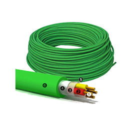
A two-core twisted pair data cable (bus cable) is the most common communication medium for KNX in smart building (BMS) installations. Here all devices are connected with one another via the bus cable. Twisted pair cables are cost-effective to buy and easy to install.
Power supply
In KNX TP the bus cable supplies all bus devices with both data and power. The rated voltage of the bus system is 24 V, while the voltage provided by the power supplies is 30 V. The bus devices work without error at voltages between 21 V and 30 V, so a tolerance range of 9 V is available to compensate for voltage drops in the cable, and contact resistance.
In the devices, the DC supply voltage is first of all separated from the data carrying AC voltage. The DC supply voltage is created by a capacitor, while a transformer decouples the data-carrying AC voltage. In transmitting devices, the transformer also serves to superimpose the outgoing data onto the bus voltage.
Data rate and signal shape
the data transfer rate is 9,600 bit/s, and the data travel serially, one byte at a time, via asynchronous data transfer. When a logical zero is transmitted, the voltage drops briefly and then, after no more than 104µs, increases again to even out at the original voltage. This is due to the inductor effect of the choke. The transmission of logical ones corresponds to the idle state of the bus (Fig. 5).
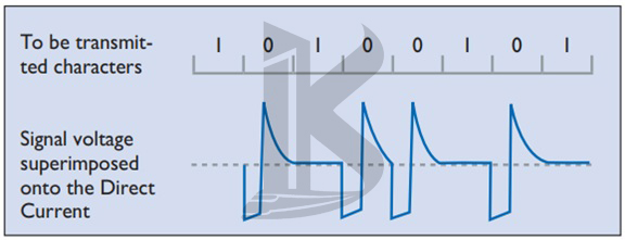
Figure 5. Signal shape in TP KNX in smart building (BMS)
An important feature of communication via TP KNX in smart building (BMS) is that the signals are coupled symmetrically onto the bus, i.e. the data cable has no fixed reference point against earth. This kind of communication is known as symmetrical, non-earthed transmission. The receiver does not register the voltage to earth in an individual data cable (like e.g. in the USB port), but instead evaluates changes in the voltage difference between the two data cables (Fig. 6).
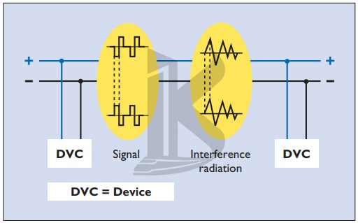
Figure 6. Symmetrical data transfer
This means that, without any significant additional hardware, stability against coupled interference signals increases significantly, because e.g. the interference signals on both cores counterbalance each other (differential). The transmitter creates the AC voltage corresponding to the logical zero by only sending a half-wave, which it does by lowering the voltage on the pair of cores in the data cable by around 5 V.
After approximately half a bit period, the sender cancels this voltage drop again. The rest of the system – the bus cable, transformers and charging capacitors of all bus devices, and very importantly the choke of the power supply, then generates a positive compensating pulse (resonator).
Telegram structure
Information is exchanged between bus devices in the form of so-called telegrams. A telegram consists of a sequence of characters, with each character consisting of eight zeros and ones, in other words eight bits, or one byte. Often several characters are combined with one another to form a field. TP KNX in smart building (BMS) telegrams have four fields (Fig. 7):
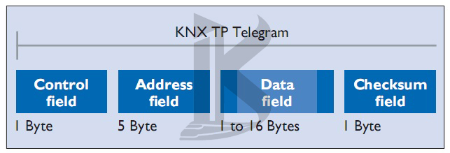
Figure 7. Telegram structure in TP KNX in smart building (BMS)
- The control field defines the priority of the telegram and whether or not transmission of the telegram was repeated (if the receiver did not respond)
- The address field specifies the Individual Address of the sender and the destination address (Individual Address or Group Address) of the receiver
- The data field, which can be up to 16 bytes long, contains the telegram’s payload
- The checksum field is used for parity checks
Bus access method
Access to the KNX in smart building (BMS) bus, like several other bus systems, is random and event-driven. A telegram can only be transmitted if no other telegram is being transmitted at the same time. To prevent collisions during transmission, the priorities of the various sending devices are regulated by the CSMA/CA (Carrier Sense Multiple Access/ Collision Avoidance) method (Fig. 8).
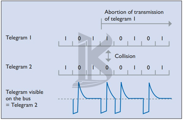
Figure 8. Collision avoidance in KNX TP
Each transmitting device listens in to every bit of data transfer along the bus. If two devices are sending a telegram at the same time, then inevitably (and no later than at the moment of transmission of the sender address in the address field), one sender will transmit a 0 while the other wants to transmit a 1. The device sending the 1 “hears” that a 0 is being transmitted along the bus, and detects the collision.
It is obliged to abort its own data transmission and give priority to the other transmission. After the transmission taking priority is complete, the aborted data transmission recommences. A telegram’s level of priority can be defined in its control field; this enables the designer of the system to specify which telegrams have “right-of-way” in case of collision. If two telegrams have the same level of priority, which telegram is allowed to be sent first is determined by its physical address (0 has priority over 1)
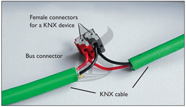
Connection of bus devices
Bus devices are connected to the data cable via components known as bus terminals – plugin terminals able to accommodate up to four KNX cables. The bus terminals make it possible to disconnect devices from the bus without interrupting the bus line. This represents a key benefit of the KNX in smart building (BMS) bus system: removing a single bus device from the system does not stop the other devices from communicating with one another (Fig. 9).