Serial data transmission and KNX protocol in smart building
Fundamentals of Serial Data Transmission in smart building
1.1 Introduction and Terminology in smart building
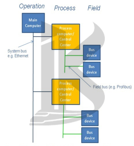
1.1.1 Hierarchical Problem Division Hierarchical division
Expediently solves the variety of tasks that arise from the automation of machining or operational procedures in smart building. The hierarchical levels take on the following tasks for example:
Main computer:
In the smart building system All Manufacturing (or Material) Requirements Planning (MRP) and Production Control is done at this stage. This is, among other things, manufacturing planning resulting from requirements for production planning / scheduling as well as central production control. It is therefore necessary to feed condensed production-specific data from the process level back to the main computer
Process computer Control centre:
These control one section of the manufacturing process. In car manufacturing, such plant sections could be the car body production line, the paint line, the assembly of the drive mechanics, etc. The process computer is responsible for data acquisition and compression, for monitoring and optimisation.
Field level:
This could for example be a programmable (logic) controller (PLC) with all the sensors and actuators, or intelligent sensors and actuators, connected to it.
1.1.2 Hierarchical Structures
The hierarchical division of tasks leads to the hierarchical structure of the communications networks In the discussion of building intelligence used in plants and installations. The demands made on the network are different at each level.
Relatively small amounts of data are processed on the field level but uncontrollable delays in data transmission cannot be tolerated at this level of the automated installation.
1.1.3 Where are the BUS systems used in building intelligence in this hierarchy?
The networks used in automated building installations are typical field bus systems (sensor-actuator-bus).
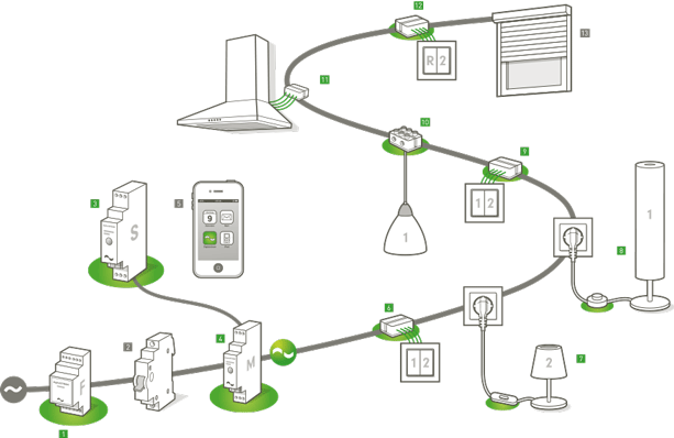
Home Intelligence
Figure 1: Where do we find the building systems buses?
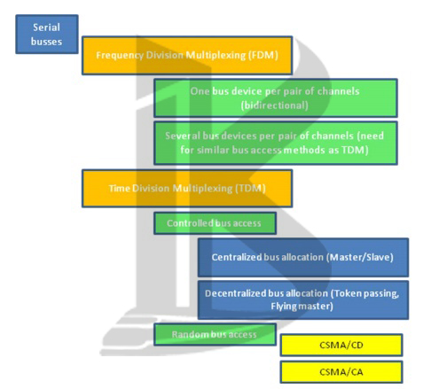
1.1.4 Classification of Serial Buses
According to their methods of data transmission and bus access:
building intelligence
Figure 2: Classification of Serial buses
Frequency Division Multiplexing (FDM)
The messages to be transmitted modulate the carrier frequencies, either by amplitude or frequency modulation. One bus line can therefore transmit several channels (different frequencies) each of which allows data traffic independently of the others.
Time Division Multiplexing (TDM) certain time slices are allocated to each message or channel, i.e. the bus devices may only use the bus one after the other. With TDM therefore, access to the bus must be controlled in order to prevent simultaneous bus access of several bus devices.
- Centralised bus allocation (Master/Slave)
- Decentralised bus allocation (e.g. Token Passing, Flying Master)
- combination of both access control methods (e.g. PROFIBUS)
- CSMA/CD (Carrier Sense Multiple Access with Collision Detection e.g. Ethernet)
- CSMA/CA (Carrier Sense Multiple Access with Collision Avoidance e.g. KNX,CAN)
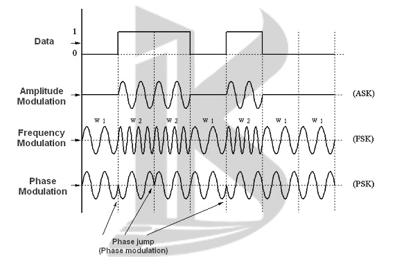
How the Shape of the Signal (Bit Representation) Changes with Modulation
A carrier frequency is modulated by the binary information to be transmitted:
smart building
Figure 3: Change of shape of signal with modulation (Bit representation)
Modulation is used both for Frequency Division and Time Division Multiplexing.
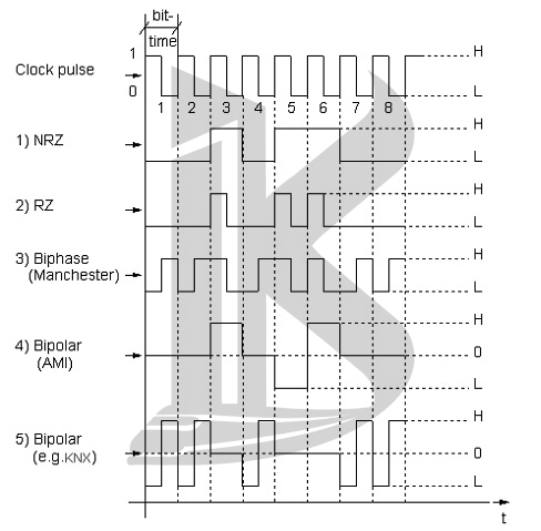
How the Shape of the Signal (Bit Representation) Changes with Baseband Transmission
With baseband transmission the binary information is transmitted in the form of rectangular pulses. This type of data transmission is used in KNX (Home Intelligence Protocol).
Typical formats of baseband transmission
Example: Consider the bit sequence 00101100
smart building
Figure 4: Change of shape of signal with Baseband transmission (Bit representation)
NRZ = non return to zero
RZ = return to zero
1.1.5 Error Detection Techniques
-
Parity (VRC – vertical redundancy check)
One bit per character, even or odd; only suitable for character-by-character data transmission as used, for example, in KNX (bms); usually applied to all start-stop transmission methods; often referred to as vertical parity. Parity checks only detect odd bit errors and not the even ones.
-
Horizontal/longitudinal parity (LRC – longitudinal redundancy check) A check digit is used which contains exactly as many bits as the characters of the transmitted information.
The bits of the check digit are derived from the associated bit positions of all characters of the information already transmitted and appended to the actual information in the form of (even or odd) parity bits.
-
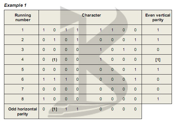
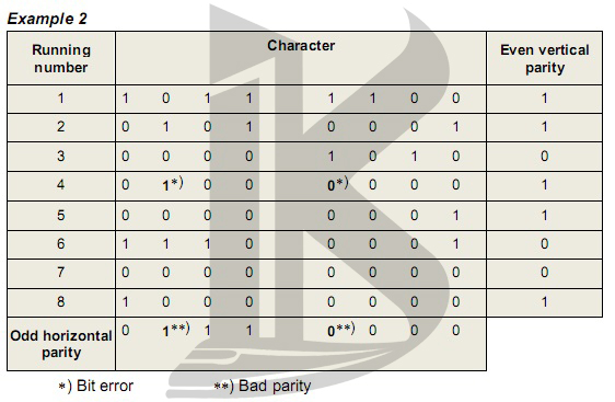
Cross check Combination of vertical and horizontal parity checking.
This type of transfer check is capable of correcting single-bit errors and detecting double-bit errors. Example: KNX (Home Intelligence Protocol) with even vertical and odd horizontal parity.
smart building
There is a single-bit error in the 4th character. This error is detected by the vertical parity check, whereas the position of the incorrect bit is recognized by the horizontal parity check. This makes it possible to correct errors.
smart building
The 4th character contains a 2-bit error which remains undetected by the vertical parity check but is recognised by the horizontal parity check.
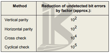
- Cyclical check (CRC – cyclical redundancy check) with this error detection method, a check digit is generated as a result of an extensive polynominal calculation. The CRC procedure detects even complex errors.
smart building
Comparison of the Different Error Detection Techniques
2 The OSI Reference Model (ISO 7498)
هوشمند سازی ساختمان ، ساختمان هوشمند ، خانه هوشمند ، بی ام اس
2.1 Introduction to the OSI Reference Model
2.1.1 Why are Standards Necessary?
When data processing systems and communication networks of different manufacturers were first introduced, there was no compatibility between them. Intercommunication between systems of different levels and standards was therefore difficult and only possible with great efforts. The multifarious networks on the market were designed for very different purposes in the industry and business sectors. Each network was a self-contained system closed to communication with another.
2.1.2 Objective of the OSI Reference Model
The International Standardisation Organisation (ISO) in the seventies therefore decided to formulate a standard architecture for computer networks and information processing. The aim was to…
- develop a standardised model in data communications on the basis of which distributed networks and systems could talk to each other,
- achieve compatibility among networks without insisting on implementation of the complete model for each network
- Achieve open communication (Open System Interconnection OSI) among all users of a heterogeneous computer network.
2.2 The Principle of the OSI Reference Model (OSI)
OSI generally specifies the functions required for data communication and the interaction between these functions. The result is therefore a hierarchical concept consisting of layers.
During the decoding of a telegram by the bus device, each layer decodes part of the telegram. During the creation of a telegram by a bus device, the grouped functions inside an OSI layer all contribute for a part to the telegram.
The above can be respectively compared to peeling off the layers of an onion to arrive to the core (= useful information) or adding onion layers to the core information.
2.2.2 The Two Types of Communication
-
Connection-oriented Communication:
The established connection constitutes a logical link between two communication partners. Both partners regard this connection as a link that only exists between them (point-to-point [P2P] connection) and that can only be used by them.
The server (= the device wishing to establish a communication) must establish this connection according to some specified criteria (quality, cost, time delays, etc.) and uses resources to do so. In addition, a protocol or parameters, such as the block length of the data, may be defined. When the connection is established, the actual data exchange (data transport) is executed according to the protocol.
The connection may be aborted at any time by any of the partners (disconnection). The resources used for the link are then released and made available to other functions.
Such communication is highly secure, but is not very bandwidth effective (i.e. a lot of communication is needed to reach only one single communication partner).
When considering the OSI model, during this communication the Transport Layer as well as the Link Layer will generate messages confirming reception of data. This type of communication can be compared to talking to one single person and checking after each question, whether he/she understood the question.
-
Connectionless Communication
This type of communication uses no connection. It is therefore not possible for the involved devices
- to agree upon a protocol or parameters
- To fix criteria such as service quality, cost, etc.
As there is no connection, the address must be sent together with the useful data after each data request. There is no confirmation of the data received and the device sending the information (=server) does not guarantee the correct order of the transmitted data blocks.
Such communication is not secure, but very bandwidth effective: there is no need to establish or break down a communication connection and with one single message it is possible to reach all devices included in the installation. However, only one common acknowledgement of receipt is received. It can therefore not be ensured that all devices have correctly received the sent message.
When considering the OSI model, during this communication only the Link will generate acknowledgements of receipt.
This type of communication can be compared to talking to a group of persons and continuing with the next question if at least one person confirms that he/she understood the message
2.3 Principle Functions of the Layers; Implementation in KNX (Home Intelligence Protocol)
2.3.1 Application Layer (Layer 7)
The application layer basically provides functions for two tasks:
- Assisting the application program in sending and receiving useful information
Implementation in KNX (bms):
KNX (Home Intelligence Protocol) is a bus using objects for communication (called ‘group objects’1, similar to CAN bus). A group object can be, for instance, the switching state, the daylight intensity or the temperature in a room.
The application program of a sensor “measures” the physical quantity (e.g. contact state, lux value, temperature, etc) and writes the value of this quantity in the appropriate group object.
At the same time it will request to the system software to send the new value of the group object on the bus in order to inform the communication partners of the sensor (BMS equipment) of this updated value.
The Application Layer of the addressed actuator(s) will ensure that new received value is written in the group object(s) concerned and subsequently inform the application program(s) of the actuator(s) of the update. The program(s) reads the value of the actuator’s group object and executes the required function accordingly. This can be the switching of a relay, reducing the light intensity of a lamp, operating a valve, etc.
Application programs in a KNX (Home Intelligence Protocol) network communicate therefore by way of group objects. Hence no connection is established for data communication (refer to “Connectionless Communication”).
Note that the application program is unable to retrieve the source of the update of the group objects!!
- Assisting devices in understanding configuration messages called ‘management services’.
During the commissioning phase of bus devices, connection-oriented communication is established between devices to download the application programs. It is the Application that will help to understand these configuration commands.
2.3.2 Presentation Layer (Layer 6)
This layer of the OSI model has the task of shielding layer 7 and the application program from the duty of having to deal with different forms of representation of the transmitted data. It interprets and, if necessary, adjusts or converts the syntax of the message.
For example, a file containing the particulars of a group of persons must be transmitted from one bus device to another. The first device uses data records containing fields in the order “name, first name”, whereas the second device uses the reverse order. In this case it would be the task of the presentation layer to ensure that each device receives the data record in the correct order; layer 6 must therefore automatically switch the order of the data record fields as required.
With field buses in general, and therefore also in KNX (Home Intelligence Protocol) , the problem of converting the form of representation in the transmitted data does not arise. Hence, KNX (bms) devices do not need an OSI layer 6.
2.3.3 Session Layer (Layer 5)
The principle task of layer 5 according to OSI is to control the communication between two communication partners. This involves:
- Opening a dialog,
- Closing a dialog,
- Aborting or interrupting a dialog,
- Continuing a dialog at a later stage,
- Picking up a dialog at a defined, backdated point of time in the event of detected errors, so that a faulty data transmission can be repeated correctly
As the messages exchanged in field buses are short (measured values), these buses require no explicit communication control. Hence, KNX devices do not need an OSI layer 5.
2.3.4 Transport Layer (Layer 4)
- Function during connectionless Communication
For connectionless communication, the Transport layer in KNX (bms systems) has the following function:
- When sending, ensuring that the value of the changed group object is sent by the link layer with the correct associated (sending) group address.
- When receiving, ensuring that the value of all group objects is updated to which the received group address is linked.
In connectionless communication, the Transport Layer is in other words responsible for checking the Association table loaded in bus devices. This table constitutes the relation between the supported group objects and the attributed group addresses.
- Function during connection-oriented Communication
In order to establish a connection-oriented communication, the initiating device will send a Transport Layer connection message, using the individual address2 of the receiver as the destination address.
During an established connection oriented communication between two communicating bus devices, the Transport Layer of both devices will make use of the Transport Layer “ACK” (positive confirmation) or “NACK messages” (negative confirmation) to acknowledge or reject received telegrams.
On reception of a NACK message from Transport Layer, rejected telegrams (negative acknowledgement) are repeated up to three times. The repetition parameter is fixed in the system software.
Connection oriented communication is monitored by means of timers. If a telegram cannot be transmitted within the set time, or if neither “ACK” nor “NACK” are received from the communication partner, then an established connection is automatically cleared down.
The connection oriented communication is also monitored with an additional sequence number (between 0 and 15). If the sequence number does not have the expected value, the receiver will automatically clear down the established connection.
2.3.5 Network Layer (Layer 3)
A network is usually a combination of nodes which are interconnected by individual links according to a defined topology. The principal task of the OSI layer 3 (network layer) of such a network is to find suitable paths for data transmission, switch the links involved and ensure that the telegrams are directed toward the destination. This is often referred to as “routing”.
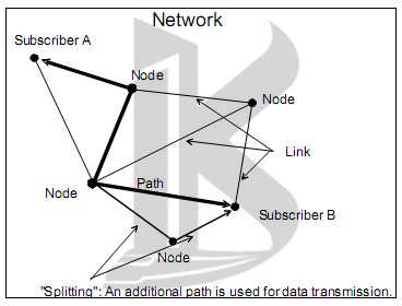
smart building
The nodes in between subscriber A and Subscriber B must ensure a “switching service”, so that the message sent by A reaches B. This is comparable to relaying calls in a public telephone network.
smart building
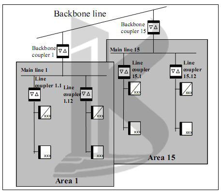
A KNX Twisted Pair (KNX-TP) network has the following structure
Figure 5: KNX TP network structure
The individual segments of the KNX-TP network (Home Intelligence Protocol) constitute the links, whereas the backbone couplers and line couplers are the nodes of the network. Loops between two lines are not permitted in a KNX-TP network.
2.3.6 Data Link Layer (Layer 2)
General Task of Link Layer
According to OSI, this layer has the task of ensuring the “error-free” transmission of telegrams within a link, i.e. between two nodes of a network (read for KNX (bms system): line or backbone couplers) or between a bus device and a node.
Hence information such as synchronisation characters, sequence numbers, error check field and other control characters are included in telegrams, in addition to the actual data to be transmitted.
2.3.7 Physical Layer (Bit Transmission, Layer 1)
The lowest layer in the OSI Reference Model is called the physical layer. This layer is concerned with the nature of the signals. It has the task of identifying the bits received from layer 2, converting them to physical signals such as voltages, currents and electromagnetic waves (radio or optical signals) and finally transmitting these signals over the bus transmission media (copper cable, optical fiber etc).
Principal aim of the services provided by layer 1 is to shield layer 2 from the physical means used for bit transmission. It is thus ensured that the upper layers of the network remain independent of the transmission physics used, so that principally the transmission media could be changed without having any effect upon the upper layers. The physical layer contains the protocol, defines the cabling and wiring between devices and contains the specifications for electromechanical components such as plugs and connectors.
The bit transmission layer of the KNX (Home Intelligence Protocol) network is characterised as follows:
The KNX-TP network comprises one or several electrical segments. Each segment has one or two power supplies but – as per definition – does not contain any line couplers.