Powerline (PL) KNX in smart home
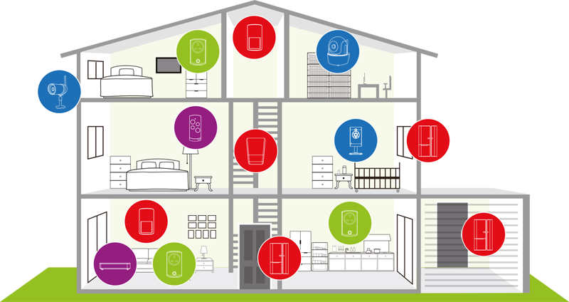
Using the existing electricity cables in a building as the KNX communication medium is a cost-effective way of retrofitting a building with KNX. In KNX Powerline ((PL) KNX in smart home) there is no need to lay a dedicated bus cable: the electricity cables already installed (one of the three phases + the neutral wire) themselves become the communication medium. The data signals are superimposed on to the mains voltage.
Power supply
No additional power supplies are needed for (PL) KNX in smart home; the power required by the bus devices comes from the 230 V mains electricity grid. Phase couplers are used to ensure that data communication can take place via all three phases, while band-stop filters prevent the propagation of data signals through the building connection towards the mains grid. Alternatively, instead of phase couplers, system couplers can be used.
Data rate and signal shape
In (PL) KNX in smart home the data transfer rate is 1,200 bit/s. Logical zeros and ones are transmitted via spread frequency shift keying (S-FSK).A signal of frequency 105.6 kHz sent by a transmitter corresponds to a logical zero, while a logical one is represented by a frequency of 115.2 kHz (Fig. 10).
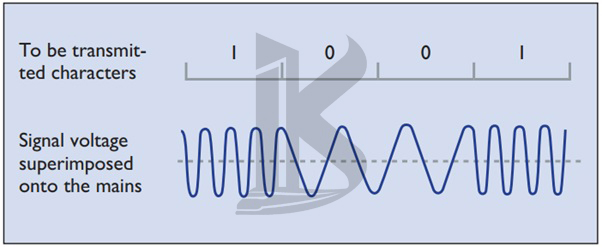
Figure 10. Signal shape in KNX PL
The signals are superimposed onto the mains voltage. Thanks to comparative techniques and an intelligent corrective procedure, signals received can be evaluated even when interference is present. The centre frequency of the two wave motions is 110 kHz, which is why the (PL) KNX in smart home system is also known as PL110. The transmission power of the superimposed signals is often equal to the level of noise on today’s highly noise-polluted mains networks. As a result they can only be evaluated using special digital signal processing methods, in which the transmission power and receptive sensitivity of the bus devices are constantly adapted to the network conditions.
Telegram structure
KNX PL telegrams are essentially extended KNX TP telegrams. (PL) KNX in smart building telegrams have four fields (Fig. 11):
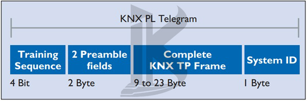
Figure 11. Telegram structure in KNX PL
- The training field synchronises and sets the levels of senders and receivers
- The preamble fields indicate the start of transmission, control access to the bus, and are needed to prevent telegrams from colliding
- The third field contains the KNX TP telegram
- The system ID field contains an ID for keeping the signals of different (PL) KNX in smart home systems separate, so that only devices using the same system ID can communicate with one another.
Bus access method
Like KNX TP, KNX PL requires the use of a bus access method to prevent collisions between telegrams. This can only be done by delaying the sending of telegrams by bus devices. The default state of all bus devices is receive mode; only if certain conditions are met are they able to switch to sending mode. If a device detects the bit string of a preamble, this indicates to it that the bus is occupied by another device. A differentiation is made between the two states Bus occupied and Bus blocked. If a device receives a Bus occupied signal, the transmission of its telegram is postponed until a later point in time, chosen at random from one of seven possible options. This hugely reduces the likelihood of collisions occurring.
Connection of bus devices
In (PL) KNX in smart home , bus devices are connected directly to the 230 V mains network.