KNX topology in smart home
KNX topology in smart home – KNX systems can be added to as desired, and can consist of several KNX subsystems based on different communication media (TP, PL, RF, IP). To ensure problem-free transmission of telegrams between individual bus devices, KNX systems must adhere to a specific topology.
KNX TP Topology
The basic unit of a KNX TP installation is a line (Fig. 19).
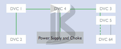
Figure 19. KNX TP line
A line includes a KNX power supply (including choke), and usually no more than 64 other bus devices. The power supply and twisted pair line (bus cable) perform two functions: they supply the bus devices with the power they need, and permit the exchange of information – i.e. the sending of telegrams between those devices. The bus cable can be laid as desired, and branches can be added at any point.
The resulting topology is a free tree structure, which allows a great deal of flexibility in terms of layout. Line Repeaters can be used to extend a line if more than 64 devices are needed. Sections added in this way are known as line segments. A line segment consists of a line repeater, a power supply (including choke), and no more than 64 further bus devices (line repeaters count as bus devices in the line).(KNX Topology in Home Intelligence)
No more than three repeaters can be operated in parallel in a line, meaning the maximum number of bus devices is 255 (Fig. 20).
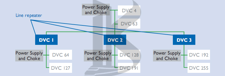
Figure 20. Maximum length of a line in KNX TP
Another way of expanding the installation is to create new lines using Line Couplers. Because, in practice, line repeaters and Line Couplers (or Area Couplers) are often the same hardware, lines are not normally extended to their maximum size using line repeaters; new lines are generally created instead.
On the one hand this makes the system more manageable, and on the other hand it reduces the number of telegrams travelling along each line (by taking advantage of the filter function of the line couplers).
A Line Coupler will not send a telegram to a line for which it is not destined. Up to 15 lines can be operated via Line Couplers on a line – the main line – to form an area (Fig. 21).
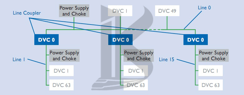
Figure 21. An “area” in KNX TP: up to 15 lines can be coupled via a main line.
KNX topology in smart home – The main line can likewise accommodate up to 64 devices. Line Repeaters cannot be used on the main line. Line Couplers in the main line count as bus devices. Each line needs its own power supply (including choke).
Up to 15 areas can be added to an area line via Area Couplers, to form a complete system (Fig. 22).(KNX Topology in Home Intelligence)
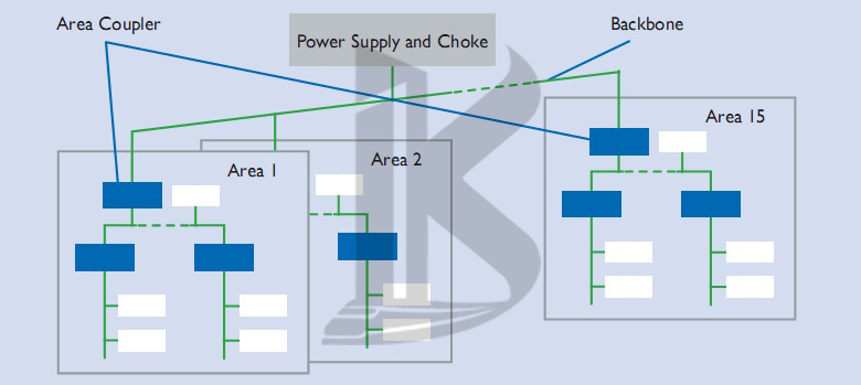
Figure 22. Up to 15 areas can be coupled via area couplers in KNX TP
Just like the main line, the area line can accommodate up to 64 bus devices (not including Line Repeaters). Line Couplers on the area line count as bus devices. In practice, area coupling is typically performed using Line Couplers parameterized as area couplers.
The area line is also called the backbone, so it also needs its own power supply. The separation of the system into lines and areas has the following substantial benefits:
-
More reliable operation thanks to galvanic separation – lines and areas all have their own power supplies. The system as a whole continues to work even if individual power supplies fail.
-
Local data traffic on a line or area does not affect the data rate in other lines and areas.
-
The topology is logical and manageable for commissioning purposes.
Cable lengths
For signal formation reasons, and due to the maximum permissible propagation delay, distances in line segments are limited as follows:
- Distance from power supply to device: max. 350 m
- Distance between any two devices in a line: max. 700 m
- Length of a line segment: max. 1,000 m
- Distance between two power supplies (including choke) in a line: as per manufacturers’ specifications.
Individual Addresses
Every device in a KNX system is assigned a unique, unambiguous number – its Individual Address. This consists of three numbers separated by dots. The numbers depend on the position of the bus device in the topology:
- The first number denotes the number of the area
- The second number denotes the number of the line
- The third number is a sequential number indicating the device’s position in the line. Physical addresses are needed in order to identify devices clearly, and also to program them. A special point to note is that, when attributing physical addresses, area/line couplers must always be given the number 0 as their sequential number.
Examples: Physical address 1.1.0: line coupler coupling the first line with the main line in the first area. Physical address 2.3.20: bus device 20 in the third line of the second area.
KNX PL Topology
The topology in KNX PL is similar to that of KNX TP, and is made up of lines and areas. The basic unit of an installation is a line containing a maximum of 255 devices. An area is created by coupling 15 KNX PL lines using KNX TP; in PL the maximum number of areas is eight, however.
Instead of line couplers, in KNX PL system couplers are used. The individual KNX PL lines need to be separated from one another using band-stop filters. System couplers, like all other couplers, have filter functions, which make it possible to reduce the number of telegrams in the various subsystems. Because the number of telegrams in a KNX PL installation is considerably smaller than in KNX TP, using KNX PL can be a necessary measure for preventing congestion in the bus system.
Individual Addresses in smsrt home (bms)
System couplers (like Area and Line Couplers) are assigned the sequential number 0. All other PL devices are assigned a Individual Address corresponding to their position in the topology.
Examples: Individual Address 1.5.0: system coupler coupling the fifth PL line with the TP main line in the first area. Individual Address 2.3.20: PL bus device with sequential number 20 in the third line of the second area.
KNX RF Topology
The devices in a KNX RF installation do not need to be arranged hierarchically, and can be installed virtually anywhere. Provided that they are within range of one another, any sensor can communicate with any actuator. It is not possible to limit the range of RF radio signals geographically, i.e. KNX RF telegrams can be received by devices in other, nearby KNX RF installations. It therefore needs to be ensured that neighbouring installations cannot interfere with one another. Telegrams sent by KNX radio transmitters always include the serial number/domain address of the device as a unique identifier. Only those receivers paired with the transmitter are able to process telegrams sent by it.
A KNX system can be purely a radio network, or can combine radio with another communication medium (e.g.KNX TP). Media Couplers are used for coupling purposes.
Individual Addresses
KNX topology in home intelligence – Media couplers are assigned physical addresses corresponding to their position in the system topology. Physical address 2.3.20: media coupler with sequential number 20 in the third line of the second area.
KNX IP Topology
KNX IP can be used in place of main and area lines. This requires the use of KNXnet/ IP routers. On the “top” of KNXnet/IP routers is an Ethernet port and a KNX TP connection. The routers forward KNX telegrams to other KNXnet/IP routers using the routing method. The availability of Ethernet as a further communication medium increases yet further the flexibility of KNX system topologies. KNXnet/IP routers can be used both as Line Couplers (Fig. 23)
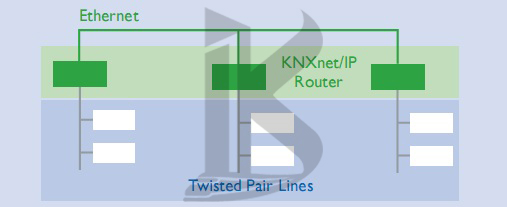
Figure 23. Coupling of KNX TP lines with KNXnet/IP routers
And Area Couplers (Fig. 24).
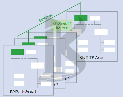
Figure 24. Coupling of KNX TP areas with KNXnet/IP routers
Like all couplers, KNXnet/IP routers are also able to filter telegrams. KNXnet/IP routers also make it possible to program devices in different lines. Some manufacturers of KNXnet/IP routers additionally support the filtering of telegrams with Individual Addresses, to prevent programming across different lines or areas if desired.
During operation, KNXnet/IProuters communicate with one another and with the other KNX devices in the system via Ethernet, using routing as a communication method. Most KNXnet/IP routers also support tunneling, i.e. they can also be used as an IP programming interface for ETS.
KNXnet/IP routers can additionally be used to connect entire separate systems with one another via Ethernet (Fig. 25).
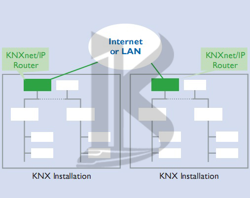
Figure 25. Coupling of two KNX systems at separate locations
This can be useful if e.g. two buildings are each equipped with a KNX twisted pair system, and these two installations need to be combined into a single system.
KNX topology in smart home – If there is already an Ethernet connection between the two buildings (which will often be the case in commercial and institutional buildings), then there is no need to lay a new cable between them.
KNX IP can also be used to network KNX devices, e.g. KNX displays, with one another. Software is available for communicating with KNX systems via KNXnet/IP.
Cable lengths
Ethernet installations are connected using network cables. Various types of network cable are available, each using a different method for shielding the cable cores. It is generally not permitted for these cables to be longer than around 100m. For longer installations, special network components are needed to join together individual network segments. In residential buildings cable length is not usually an issue. As already mentioned, in commercial and institutional buildings the existing network infrastructure can be used.
Individual Addresses
KNXnet/IP routers (routing) are given the sequential number 0 (like area and line couplers).KNXIP interfaces (tunneling) can be given any sequential number.
Examples: Individual Address 1.5.0: KNXnet/IP router acting as a line coupler, coupling the fifth line with the main line in the first area. Individual Address 2.3.20: KNX IP programming interface with sequential number 20 in the third line of the second area. (make smart)
Mixed topology in KNX Topology in Home Intelligence
All of the topologies for the various communication media (TP, PL, RF and IP) can be used in combination with one another if desired (Fig. 26).
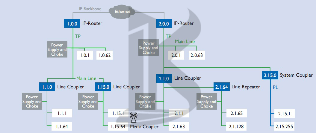
Figure 26. Example of KNX topology incorporating all media (TP, PL, RF, IP)